Building a Pentium II PC - the illustrated guide
Review date: November 1998.Last modified 03-Dec-2011.
Building an IBM compatible computer is pretty easy. You do not need to be a technical genius or serious handyperson to do it. And it can save you a fair bit of money over having your local clone shop knock a computer up for you - not to mention let you shop around for exactly the components you want.
For this tutorial, though, I deliberately haven't shopped around much. This PC's got rather a lot of of Diamond Multimedia Systems components; since you can now buy Diamond motherboards, sound cards and video cards, and since a lot of buyers stick as much as they can to one recognised brand, I thought it'd be interesting to see what you get when you do.
You don't actually need to get a lot of componentry from the one manufacturer if you don't want to. Compatibility between different PC component makers has been superb for some time, so just about anything currently on the market will work with just about anything else. The bad old days when IDE hard drives from different manufacturers would only work together for Mandrake the Magician are long gone.
The parts I settled on for this computer are:
Diamond Micronics C400 motherboard
This is a great, high performance, well documented, well labelled board, ideal for first time PC builders. Read my full review of it here.
Diamond Monster 3D II 3D accelerator
3DFX's Voodoo 2 chipset is still hanging in there in the 3D accelerator market. Anybody who installs a Voodoo 2 card in a computer with a Riva TNT card is going to have a hard time explaining why, but since it works with the Viper in exactly the same way as it works with everything else, I did it anyway for demonstration purposes. Read my full review of the Monster 3D II here.
Diamond Monster Sound MX200
Now superseded by the MX300, the first Diamond A3D sound card is still a top flight performer. Read the full review here.
Diamond Viper V550 video card
At the time of writing, this is pretty much the fastest 2D/3D combination video card you can buy. Read my full review of it here. If you're into overclocking or just live somewhere hot, check out my simple instructions for adding a cooling fan to the V550 here.
In Win Q500-ATX case
A good choice for people who intend to put a lot of equipment in their PC, or just want to pose a bit. Read my full review of the Q500 here.
For a regular home or small office computer, I recommend a midi-tower case. Mini-tower and desktop cases may have enough drive bays for your needs, but their cramped design makes the interior one big cable knot, and reduces cooling airflow. Midi-tower cases have enough space for all but the most macho power users, good airflow, and are less likely to herniate you if you have to lug them around.
Whatever case you choose, get a good one. Cheap stamped metal cases are pigs to work on - anyone who's ever installed a car stereo with stamped metal mounting hardware and come away with lots of little cuts on their hands will know why. Apart from sharp edges, cheap cases also commonly have lousy screws that break or strip, poorly tapped screw holes that cause screws to jam, and any number of other annoyances. It doesn't cost much more to get a quality case, considering the overall price of a whole new computer, and if you're the one that has to work on it, it's worth paying extra.
Intel Pentium II 350MHz CPU
I, personally, am a big fan of overclocked Celeron processors for home computers, but since they're not quite a plug-and-go proposition, a proper Pentium II 350 is a decently fast and not too pricey alternative for people who don't want to fuss around running things faster than the label says. Mind you, a Celeron 333 run at its rated speed is not a lot slower than the P-II 350, and notably cheaper.
64Mb PC100-certified SDRAM
Since I don't intend to push this computer beyond 100MHz front side bus (FSB) speed, any old PC100 SDRAM will do.
Fujitsu MPC3032AT 3.2Gb Ultra DMA EIDE hard drive
Fujitsu's drives are not encumbered with fighter-plane product names or gussied up with funny coloured frame castings. They're just fast, reliable, decently priced drives. I don't know about you, but I find this refreshing.
AOpen CD-936E/AKU 36X CD-ROM drive
Most CD-ROM drives are pure commodity items these days. AOpen's MTRP ("Maximum Transfer Rate Performance") are at the higher end of the clone scale - they read CD-RW media, they're less likely to shake like a maraca if you feed them a poorly balanced disc, and, like most current CD-ROM drives, they do audio extraction too.
Building the PC
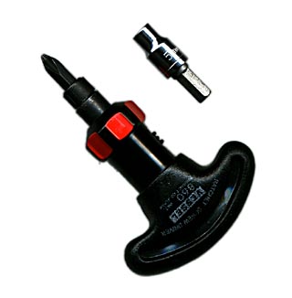
The tools of the trade. All you need to assemble a modern PC is a Phillips head screwdriver. This is my nice little Japanese made Vessel brand ratchet driver, but any old medium sized Phillips driver will do. The dingus above the driver is a 5mm socket, for tightening the hexagonal brass standoffs that the motherboard mounts onto. If you don't have such a device, don't worry, as pliers do just as well - like everything else in a PC, you don't need to do them up too tight.
If you have big meaty fingers or just aren't too dextrous, you'll also need needle-nose pliers, tweezers with serrated jaws or hemostats (my favourite) for adjusting circuit board jumpers.
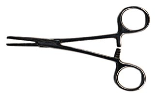
The hemostat, commonly sold as a "scissor clamp" or incorrectly referred to as forceps, is the king of all jumper-yanking devices. Be careful, though; pliers and hemostats are eminently capable of crushing the fragile plastic jumper blocks.
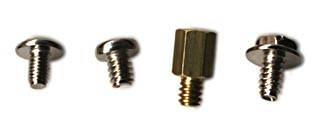
Here we have the four kinds of threaded fastener you'll get in the bag of bits that comes with your case. The one on the left is a fine-pitch screw used for mounting floppy and CD-ROM drives. The next one is a coarse-pitch screw used solely for mounting hard drives - it's shorter, to make sure it doesn't thread in too far and hit a circuit board. These screws often have a combination head - a Phillips cross with half of the cross extended to fit an ordinary slotted screwdriver, like so:

Do not fall victim to the temptation to actually use a slotted driver on one of these screws. Flathead drivers are made by people in league with hardware manufacturers, who are delighted by their tendency to skate off the screw-head and gouge valuable computer equipment.
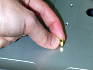
The next two fasteners have the same thread; second from the right is a hexagonal standoff that screws into the case and into which the motherboard mounting screws thread. The screw on the right is a standard Phillips head case and expansion card mounting screw.
Incidentally, if you're having trouble removing one of these last types, the hexagonal head shape outside the Phillips cross is a perfect match for a quarter inch nut driver. Quarter inch is the standard size for all hexagonal screwdriver bits, so any exchangeable bit screwdriver, including my nifty little ratchet driver and almost any cordless screwdriver you care to name, will fit. Cheaper versions of these screws have rounded shoulders on the hex head that stop you from getting a proper grip, but most of them work well.
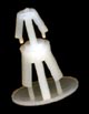
You may also get one or more nylon things that look something like this. These are another kind of motherboard standoff, and should be used wherever a roughly oval "double hole" in the motherboard coincides with a matching larger hole in the case. This one, which came with the In Win case, is atypical in that it's got two snap-fit sections, and just snaps through a round hole in the case. Many cases have keyhole shaped cutouts that the nylon standoffs slide into, the idea being that you can leave them snapped into the holes in the motherboard and just slide it across a bit and lift it out. In the real world, the motherboard usually hits the case edge before the bases of the standoffs have moved far enough to disengage.
Nonetheless, nylon standoffs are good extra support for the corners of larger form factor motherboards, which usually have at least one corner flapping in the breeze far from a mounting screw. If you forget about this and, later on, push a connector on near that corner while the motherboard's mounted in the case, you can flex the board enough to break things.
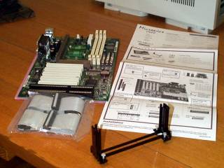
Once you've got your tools and know what each screw type is for, it's time to open some boxes and prepare your motherboard. The Diamond Micronics board came with a handy rectangle of pink foam which I sat it on while setting things up; if the board you choose doesn't come with such a luxury, a newspaper will do just fine. Remember to take anti-static precautions all through the motherboard setup procedure - once the motherboard's screwed into the computer it's pretty safe.
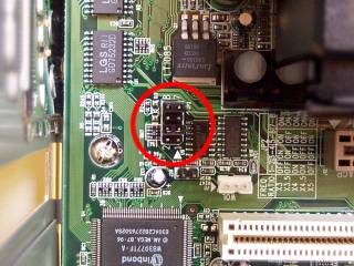
Make sure the CPU jumpers are set properly for the processor you're using. Some boards use DIP switches, teeny little switches that you can set with anything pointy, but most hardware setup boards still use jumpers, little plastic blocks with a copper conductor inside that connect pairs of pins on the board.
For many jumper-setup motherboards, you need set only one jumper block, to tell the board what speed the processor is. This is the Diamond Micronics C400 jumper block, set for a 350MHz processor. Motherboards which allow you to hand-set bus speed and/or processor voltage may need those jumpers changed, too. It'll all be in the manual.
Some motherboards allow software CPU setup; you build the computer, power it up, press delete to get into the BIOS setup menu, and tell the computer what processor it has from there.
Now's a good time to install the processor retainer, for Slot 1 processors. if you're using a Socket 7 processor, installing it on any remotely recent motherboard is as simple as lifting the lever on the socket, dropping the processor in (it can only go in one way - don't force it), and locking it in by clipping the lever back down. Pentium II class processors have to be different, and use one or another kind of mounting rail apparatus, sometimes with a brace out the side as well.
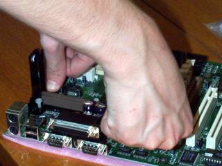
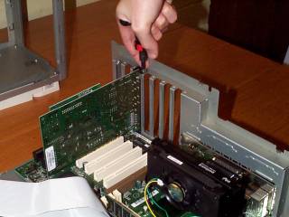
This picture shows me installing the C400's cheesy CPU retention kit. If you've got a motherboard that comes with one of these press-in retainers, don't worry, but do make sure that the expanding receivers that the press-in pins go into are pushed all the way down into the base of the retainer. This makes sure that they'll actually grab properly, and the ungainly P-II cartridge won't fall off the board if the computer's knocked. Mounting the better screw-in retainers is simple enough, especially if they're the standard kind, for which the brass screw receivers come pre-mounted on the motherboard. All processor retention kits only go together one way, so if you find yourself trying to jam something into a hole that seems too small, you've probably got something backwards.
Installing the processor itself can wait for a moment. Do the RAM next.
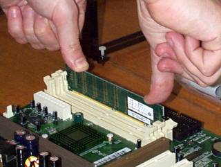
This is how to insert a DIMM RAM module, as used in all current motherboards. This computer's using a single 64Mb module. DIMMs can only be plugged in one way - there are gaps in the edge connector that mate with ridges in the socket. Push the retaining clips on the side of the socket outwards, then firmly push the RAM module down into place. It will click in, and the clips will automatically swing in to hold it. Unlike the earlier SIMM modules, you don't need to insert DIMMs at an angle and swing them into the locked position. This means that RAM sockets hard up against chassis metalwork are much less annoying - although installing all this stuff before you put the board into the computer is still the way to go.
DIMMs don't have to be inserted in pairs like SIMMs on most boards (more alert readers would have been tipped off to this by the fact that the C200 board has three DIMM sockets). It also doesn't matter which RAM socket you install the DIMM in, while SIMMs have to be installed in the lowest numbered sockets first.
Remember that RAM, while it's now normally labelled in megabytes, is still labelled on the actual chips and sometimes on the DIMMs in megabits. An "8MX64" module has a capacity of 64 megabytes, a "4MX64" is 32 megabytes. You can install DIMM modules in any combination.
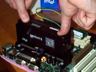
Installing the processor. Simply push down firmly until it clicks into place. The design of the edge connector only allows it to be plugged in one way. If you need to remove it again, you'll have to push the clips on the sides in and give the processor cartridge a firm tug. Again, some retention kits are different and have little locking arms or push-in devices over the top. None are very difficult to remove if necessary.
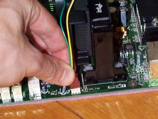
Connecting the Pentium II's heatsink fan to the header on the motherboard. If you don't do this, your processor will overheat after ten minutes or so and your computer will crash, over and over again. Actual damage to the processor is unlikely, but damage to your sanity is eminently possible.
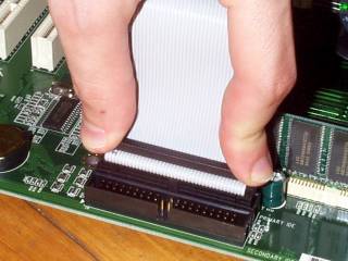
Attaching the floppy cable. Most motherboards have keyed connectors for the drive cables, which makes it impossible to plug them in the wrong way around, provided the connectors on your drive cables are also keyed. If your board or cables aren't keyed, just make sure the side of the cable with the red stripe on it is plugged into the side of the connector with pin 1 on it. There should be an annotation, commonly only legible to persons with Kryptonian eyesight, on either the board or the connector indicating which end has pin 1.
Incidentally, unkeyed connectors generally have a couple of faint moulded lines where the key block would normally be. Look for the ghost of a key, and you can tell which way the connector should go. Provided, of course, you're plugging it into a keyed socket.
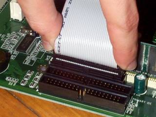
Attaching the IDE cable for the hard drive and CD-ROM drive. The same rules apply as for the floppy cable; striped side is pin 1.
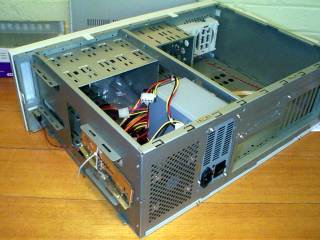
Time to open your case. In common with many full tower cases, you take this In Win apart by removing the top cap first, and then sliding off the side panels. New cases typically have their power cable, screw bag and other bits and pieces stuffed inside them. This is looking at the top rear corner of the laid-down case; on the right hand side of the corner you see the rear exhaust fan, and on the left hand side of the corner is the top back 3.5 inch drive bay, to which are cable tied the various rear panel cutout plates. Let's pick the right one.
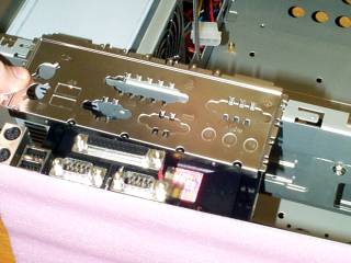
The C400, in common with many current boards, has its serial, parallel, PS/2 and USB ports all built into the motherboard. They poke out the back of the case through one of these custom panels.
ATX cases have interchangeable rear panel cutout plates to suit different kinds of motherboard. This is the most common kind, and some cases come with this one already fitted - you may need to push out the metal cover on a couple of the holes, like the rightmost serial port and two USB slots on this one, but that's it. If your case doesn't come with the right cutout installed, you'll have to snap it in yourself.
OK, so maybe you will need another tool. In this case, the rear-panel insert was a teensy bit hard to snap into place, so I encouraged it with a solid push from a Big Fat Slotted Screwdriver.
If you're using a motherboard that doesn't have some or all of these built-in connectors, you'll need to hook up cables to headers on the motherboard for all of the extra connectors. The connectors often come on an appropriately punched expansion card-type slot cover, which can be screwed over the opening for an empty expansion slot. If you don't want to block any slots, most cases have cutouts or push-out panel holes which accept the standard nine pin serial and 25 pin parallel ports. You'll have to unscrew the port connectors from their slot cover (they're held on with screw receivers not unlike the hexagonal motherboard mounting thingies, but smaller) and screw them into the case holes.
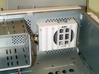
Before you mount the motherboard in the case, you should add any extra fans. Like all decent cases, the C400 has a space for another 80mm fan at the front, below the 3.5 inch drive bays. No fan is provided as standard, but fitting one is a snap-and-go operation, if you get a fan with a standard power connector already attached. If not, you'll have to solder on a power connector, or splice the fan wires into one of the power supply's existing cables.
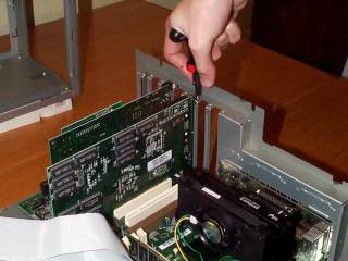
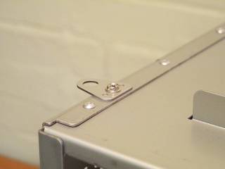
Preparing the case to receive the motherboard. Thread the motherboard screw mounts into the appropriate case holes by hand...
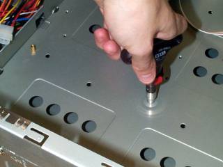
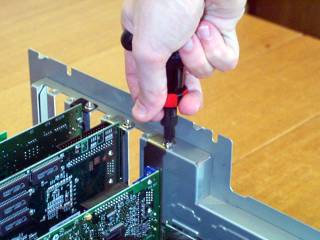
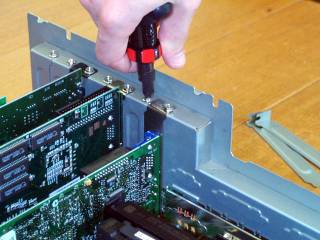
...and then tighten them with your 5mm nut driver or pliers. Remember, there's no need to wrench on them as if you're bolting a wheel onto a truck.
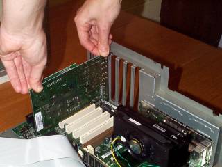
Mounting the motherboard. Slide it until its mounting holes line up with the hexagonal standoffs and its ports, if any, poke out through the matching holes in the back panel insert. Then screw it in, remembering to use the right screws - not the fine pitch ones that probably have combination heads.
The In Win Q500 case, like many better cases, has a "motherboard tray" that lets you slide the whole motherboard and all of its expansion cards right out of the computer for easy access. I could have slid it out to mount the motherboard, but it's not much easier that way and since many cases don't offer this luxury, I left it in to show you what it looks like for the common folk. It's easier to photograph with the tray out, though, so I removed it after this step and put it aside. Drive time.
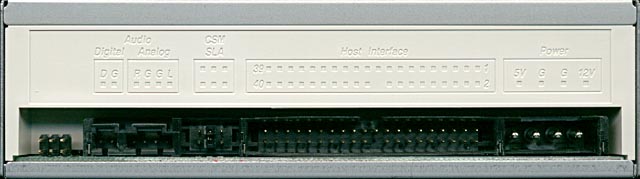
Before you mount the drives in the case, check the CD-ROM and hard drive to see what their master/slave settings are. EIDE devices have a controller built right onto the drive, and if you want to use two of them from one IDE channel on the motherboard, you need to set one drive to master and the other to slave, so that the master drive's controller controls both drives.
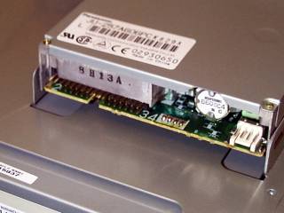
On the CD-ROM rear panel shown above, the master/slave jumpers are the things to the left of the 40 pin IDE connector, itself to the left of the big four pin power connector on the right hand side.
Since CD-ROM drives normally come pre-set to "slave" and hard drives normally come pre-set to "master", you're unlikely to need to change any jumpers to make them both work on the one cable. If you decide to use both of your motherboard's IDE channels, you'll need to get another IDE cable and set the CD-ROM to master, which in most cases simply involves pulling off the single jumper it comes with.
I've mounted the floppy drive, which goes in the topmost front 3.5 inch bay for standard tower cases, and am screwing in the CD-ROM. I'm putting the CD-ROM in the top 5.25 inch bay because there's no push-out metal faceplate for that bay in this case, just the plastic bay cover on the front panel. The plastic covers can be quite hard to remove on some cases, but a solid tap from the inside with that big screwdriver which I should just give up and make part of the standard toolkit will do the job.
Remember to use the right screws for the floppy and CD-ROM drives - the fine pitch ones.
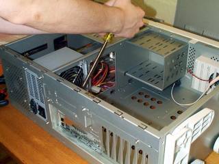
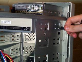
Screwing in the hard drive. You can only get at this side of the drive cage by sliding out the motherboard tray - unless you remove the whole 3.5 inch cage. All decent cases, including the Q500, let you remove the hard drive cage, usually by removing only one screw. Again, though, I'm treating this like a cheaper case to show you where to go. Cheap cases with no motherboard tray have big holes in the motherboard mounting plate that generally give pretty good access to the shaded side of the hard drive mounting area.
As it happened, this was the wrong place to put the drive - plugging the first drive connector on the IDE lead supplied with the C400 motherboard into the hard drive left not enough cable to reach the CD-ROM, perched way up there in the top 5.25 inch bay. I moved the hard drive up a couple of bays when I discovered this. Now it's time to turn back to the motherboard tray, and install some cards.
Inserting the first expansion card, in this case the Diamond Monster Sound MX200. Cheap cards play fast and loose with the exact specifications of the metal tab that slots into the case at the bottom and is screwed in at the top (using the hex-headed screws like the ones that hold the case together). Cheap cases can have misaligned slots, or slots the wrong size, or warped back panels.
Bad mismatches, or bent tabs, can leave you with a card you can't plug in. You should never need to bear down very hard on an expansion card to get it into its socket, and it should never want to spring out again of its own accord. If this happens, check the tab for bending. If it isn't bent, it probably needs to be; look at the card sitting atop the socket, see where the tapered bottom part of the tab is in relation to the slot it's supposed to go into, and bend it a little in the appropriate direction.
When starting to screw in an expansion card, you may have to push the top of the card towards the back of the computer to get the screw in. This is OK, provided it doesn't leave the card as tight as a bowstring. Again, remember not to overtighten the screws - they can twist the tab clockwise and put strain on the whole card.
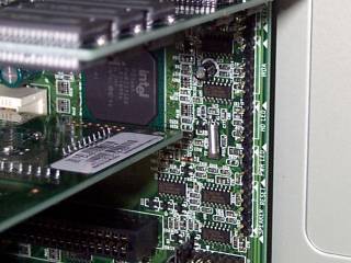
Mounting the Monster 3D II Voodoo 2 board. I've chosen to put this board in PCI slot two (you count the slots from the AGP slot end), purely in order to maintain some air space between it and the Riva TNT-powered graphics card. Both of these cards run rather hot, and can use the extra cooling.
PCI slot one on most motherboards shares an interrupt request (IRQ) with the AGP slot. For the vast majority of hardware, including this Voodoo card, this doesn't matter at all - most cards can work just fine by sharing the IRQ. The notable exception is many network cards. If you have a PCI network card and an AGP graphics card, don't put the network card in PCI slot 1.
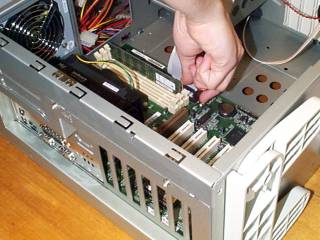
Screwing in the Diamond Viper V550 graphics card. Mounting a card in an AGP or an old ISA slot is basically the same as mounting a PCI card. Some AGP cards can be a disturbingly tight fit, even when the metalwork lines up perfectly. It's OK to wiggle them fore and aft a bit as you push them in.
The In Win case comes with blank rear panel slot covers that you can screw in for a neater look and, possibly, better overall cooling airflow, although this depends on the number and kind of other fans in the case. Most cases have some kind of press-in stamped metal covers over all of the rear panel slots by default, and you have to pop the covers off the slots you intend to use.

Sliding the motherboard tray back in, to plug in all the cables.
Bear in mind that sliding out the tray does not magically unplug the drives and power connector and LED and switch wires once you've built the computer. It will unplug them in a decidedly unmagical way if you forget about them and just whisk the tray out.
This floppy drive has the decency to clearly label the sides of the connector - the "2" and "34" printed beneath the projecting header at the left of the drive are the pin numbers nearest the printing - pin 1 is at the top left, pin 2 at the bottom left. So you connect the pin-1, striped, side of the edge connector on the end of the floppy cable to the low-numbered side of the drive header. If you connect the floppy drive to the middle connector on the cable, it'll be identified as drive B instead of drive A (the twist in part of the cable between the connectors is what identifies the drives).
The drive with cables connected. The floppy drive is the only one that uses the smaller Berg power connectors from the power supply; all other drives use the chunkier Molex versions, as shown below. Both kinds of connector are keyed - you can only plug them in one way.
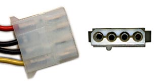
In case you're interested, the yellow wire is +12V, the red wire is +5V, and the black wires are both grounds.
These connectors are easy enough to attach, but sometimes stick fast in drive power sockets. The sockets are only held onto most drives by solder, so don't go nuts trying to wrench a seized power connector out. Prolonged fairly gentle wiggling should do the job.
What kind of cable you need to connect the CD-ROM drive's audio out to your sound card varies depending on what you've got at each end. Most CD-ROMs have a simple unkeyed four pin header, in this case thoughtfully labelled R-G-G-L, for Right, Ground, Ground, Left. The right signal wire is red, the left signal wire is white, the ground wires are black. Don't worry if your cable only has one ground wire.
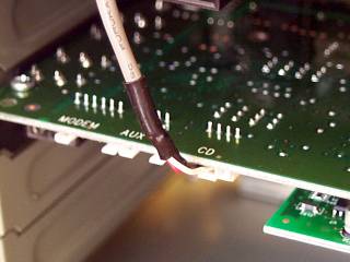
The other end of the CD audio cable is subject to the most variation. In the case of the Diamond Monster Sound card in this PC, it uses a plain keyed Sound Blaster-type connector. Check your components to make sure there's an appropriate CD audio cable provided with the sound card or CD-ROM. If there isn't, you can still finish building your PC, since all you'll be missing is CD sound. Don't sweat it; grab the right cable later.
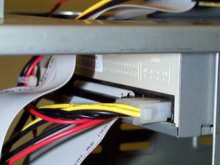
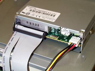
The IDE and power cables connected to the CD-ROM drive. As the device furthest from the motherboard, it gets the last connector on the cable, while the hard drive gets the middle connector. This doesn't matter, though; an IDE lead can have either of its connectors hooked up to the master drive, and still work as long as you get the connectors the right way around.
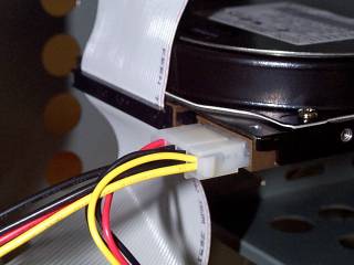
The hard drive in its new, higher, home, with power and IDE cable connected.
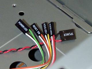
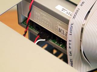
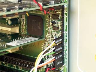
This In Win case has clearly labelled LED and switch connectors. This is not a common feature. You can identify unlabelled connectors by tracing them back to what they connect to on the front panel and remembering that the coloured, as opposed to white or black, wire is the positive one, meant to go to the first pin of the motherboard header. The headers on the motherboard are invariably labelled, but often rather cryptically.
The C400 motherboard is an exception. The LED and switch connectors are all in one row and clearly labelled. The single row is also unusual. You usually have to put up with at least a two-by-something block of header pins, with some of the pins somewhere else.
Plugging LEDs in backwards won't hurt them, they just won't light up. Connectors have one side with a couple of little bits of metal visible through gaps in the plastic housing, and another side that's solid plastic, which is where the identification is printed, if there is any. You're fairly likely to get them around the right way if you just install them with the solid side towards the nearest edge of the motherboard, but there's no guarantee. Coloured wire positive.
The Q500 case plugged into the C400 motherboard. Note that, in this case, all of the connectors are aligned the same way - text side out. Lovely.
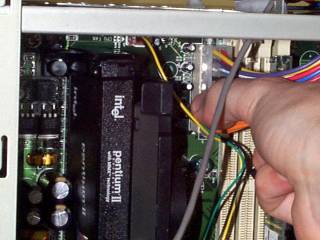
Plugging in the power connector. This is an ATX power connector, which is one big plug that can only be connected one way. If you're using an older AT-type motherboard you'll need to use the older style power connector, which comes in two parts, as shown below:
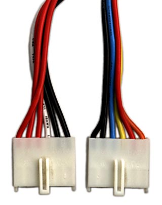
The AT power connector should always be plugged in as shown here, with the black earth wires at the middle of the double-connector. Getting this wrong can fry your motherboard.
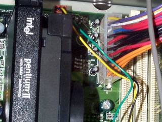
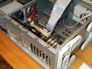
The ATX power connector in place The green and yellow wires are for the CPU heatsink fan. You did remember to plug in the heatsink fan, didn't you?
Now you're pretty much finished. Some cases, like this In Win, have some kind of security lock. It's often a lousy little wafer tumbler lock that anyone with a screwdriver can force, but the In Win has this piece of metal that screws onto the top of the frame, pokes out through the back of the top cap and can have a padlock clicked onto it. You might as well install this last, otherwise you'll probably smack your elbow on it or something.

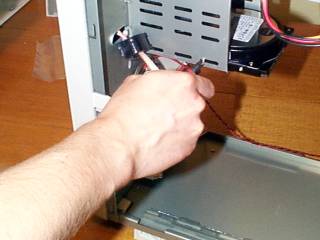
The pass-through cable for the Monster 3D. If you're using a Voodoo card, the passthrough cable should be the last thing you add to the computer, to avoid it snagging on things or getting squished as you move the case around. The cables are actually surprisingly durable, but the connectors on the boards can be damaged if the cable's yanked or crushed.
That's it! Now it's time to plug the computer into a monitor and the wall and turn it on, to see if it beeps and displays something. Leave the case panels off while you do this, in case you have to fiddle some more. If it counts its RAM and gives you a system summary and then complains about not having an operating system, you're in business, and it's time to boot from a floppy (or the CD-ROM, if your BIOS supports it and you have an appropriate disc), partition and format the drive and install your operating system.
Don't know how to do that? Check back in the future - I'll have another tutorial up on that subject soon!